Share
Pin
Tweet
Send
Share
Send
Of course, you can buy a ready-made memory. On sale now there are a great many for every taste. But their price is unlikely to satisfy a beginner hobbyist or someone who is able to make a charger with their own hands.
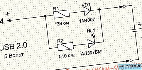
I decided to repeat this scheme, but make a charger to charge two batteries at once. The USB 2.0 output current is 500 mA. So you can safely connect two batteries. The modified scheme looked like this.

I also wanted to be able to connect an external 5 V power supply.
The circuit contains a total of eight radio components.

The tool will require a minimum set of amateur radio: soldering iron, solder, flux, tester, tweezers, screwdrivers, knife. Before soldering the radio parts, they must be checked for serviceability. For this we need a tester. Resistors are very easy to check. We measure their resistance and compare with the nominal. On how to check the diode and LED there are many articles on the Internet.
For the case I used a plastic case measuring 65 * 45 * 20 mm. The battery compartment was cut out of a Tetris children's toy.

I’ll tell you more about the alteration of the battery compartment. The fact is that initially
the pros and cons of the battery power terminals are set the opposite. But I needed that in the upper part of the compartment there were two insulated positive terminals, and at the bottom one common negative. To do this, I moved the lower plus terminal to the top, and cut the total negative terminal out of tin, soldering the remaining springs.


As a flux when soldering springs, I used soldering acid in compliance with all safety rules. The place of soldering must be washed in running water until the traces of acid are completely removed. The wires from the terminals were soldered and passed into the body through the drilled holes.

The battery compartment was fixed on the case cover with three small screws.
The board was cut out from the old Dandy game console modulator. Deleted all unnecessary parts and tracks of printed wiring. He left only the power socket. I used thick copper wire as new tracks. I drilled holes for ventilation in the bottom cover.

The finished board firmly sat in the case, so I did not begin to fix it.

After installing all the radio components in their places, we check the correct installation and clean the board from flux.
Now let's deal with the wiring of the power cord and setting the charging current for each battery.
I used a USB cable from an old computer mouse and a piece of power cable with a plug from the Dandy as a power cord.

The power cord needs special attention. In no case should you confuse "+" and "-". I have a “+” power plug connected to the central pin with a black wire with a white stripe. A "-" power goes through the black (without strip) wire to the external contact of the plug. On the USB cable, “+” goes to the red wire and “-” to black. We solder plus with plus and minus with minus. The soldering spots are carefully isolated. Next, we check the cord for a short circuit by connecting the tester in the resistance measurement mode to the plug terminals. The tester should show infinite resistance. Everything needs to be double-checked, no matter what the USB port is burned. If everything is fine, connect our cord to the USB port and check the voltage at the plug. The tester should show 5 volts.

The last setting step is to set the charging current. To do this, we break the circuit of the diode VD1 and the "+" battery. In the gap we connect the tester in the mode of measuring the current turned on to the limit of 200 mA. Plus a tester for the diode, and minus to the battery.

We insert the battery into place, observing the polarity, and apply power. In this case, the LED should light up. It indicates that the battery is connected. Next, by changing the resistance R1, we establish the required charge current. In our case, it is approximately 100 mA. With a decrease in the resistance of the resistor R1, the charging current increases, and with an increase it decreases.

We do the same for the second battery. After that we twist our body and
The charger is ready to use.
Since different finger batteries have different
capacity, it will take different time to charge these batteries. Batteries
capacity of 1400 mA / h with a voltage of 1.2 V need to be charged using this
circuits are approximately 14 hours, and 700 mAh batteries will need only 7 hours.
I have 2700 mAh batteries. But I did not want to charge them 27 hours from the USB port. Therefore, I made a power socket for an external 5 volt 1A power supply, which I was lying idle.

Here are some more photos of the finished device.


I painted the stickers with FrontDesigner 3.0. Then printed on a laser printer. Cut out with scissors, pasted the front side onto a thin adhesive tape 20 mm wide. Excessive tape was cut. I used glue stick as glue, having previously lubricated it with the sticker and the place where it is glued. How reliable this is, I don’t know yet.
Now the pros and cons of this scheme.
The plus is that the circuit does not contain scarce and expensive parts and is assembled literally on the knee. There is also the opportunity to power from a USB port, which is important for beginner hams. No need to puzzle where to power the circuit. Despite the fact that the circuit is very simple, this charging method is used in many industrial chargers.
It is also possible to complicate the circuit a little by switching the charging current.

By selecting R1, R3 and R4, you can set the charging current for batteries with different capacities, thereby providing the recommended charging current for this battery, which is usually 0.1C (battery C-capacity).
Now the cons. The biggest one is the lack of stabilization of the charging current. I.e
When the input voltage changes, the charging current will change. Also, with an error in the installation or short circuit of the circuit, there is a high probability of burning the USB port.
Share
Pin
Tweet
Send
Share
Send