Share
Pin
Tweet
Send
Share
Send
The device is assembled on the basis of an affordable ATMEGA 8 L microcontroller in a cheap TQFP32 package and an engine from a computer’s hard drive (HDD), which can be removed from an old computer hard drive. The circuit contains a minimum number of parts and can be supplemented with arbitrary functionality. It is powered by two Li-ion batteries of standard size 18650, voltage of 3.7 Volts, connected in series.
Watering is carried out in fixed portions every 24 hours.
The only button is a test of work, after pressing it, subsequent watering will be carried out exactly at the same time with an accuracy of a second. (I simply included it on vacation, no settings, so, you can offer it as a gift option, without unnecessary instructions).
Design Features:
- battery operation for several months (low power consumption);
- very accurate dosage of irrigation and exact intervals between irrigation;
- non-criticality of the circuit to details and their availability;
- lack of moving live parts in the motor, and as a result - durability and reliability when working in water;
- very low noise during engine operation;
- does not require any settings (watering once a day) with sound and light accompaniment;
- protection against deep discharge of batteries with an audible warning about the need for a charge;
- auto power off of light indication at night.
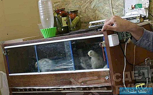
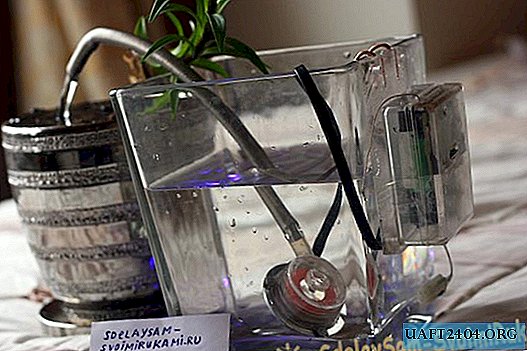
The design is a pomp (pump) immersed in a vase with an irrigation tube and a small electronics box mounted on the same vase with water.
So, for starters, let's start making the pump.
We need a CD, a plastic bottle with a volume of 1.5 liters of milk (with a wide neck, inner diameter 33 mm.), Super glue, four wires (I took the damaged wire from charging the iPhone), three screws, washers and three nuts and a piece of flexible tubing.
At the bottle and saw off the neck with a hacksaw for metal exactly along the edge of the "skirt" and align the resulting section with sandpaper, a file or a bar.

In this way we prepare the so-called working chamber of the pump.

Next, we need a CD disk, its inner hole is exactly the same size as the motor, we will make an impeller from the disk.
The disc is well cut with scissors, and it is good if it is slightly warmed up in hot water to prevent cracking of the cut edge.
We take the sawn off part from the bottle - our working chamber and apply it exactly to the center of the disk with that part where the screw cap was. Mark a circle with a marker and cut with ordinary scissors. The resulting disk will not be perfectly smooth, but the sandpaper can be corrected, the main thing is that the disk with a minimum clearance can fit inside the working chamber.
It turned out a ring of the future impeller.

Now you need to make the blades for the "propeller". To do this, you will need half the disk. We draw a marker with a strip 7 mm wide and cut it off with scissors.

Skins and level it.

Next, cut into six equal parts of 13 mm, and bend with pliers on both sides

The further procedure will require maximum accuracy, you need to glue the blades one at a time with super glue at an equal distance.
Please note that the blades are bent so that they do not rake water into the chamber opening, but rather, as if cast from the center to the hole on the edge. The motor will only rotate counterclockwise. You can slightly fix it with a droplet, align it with tweezers and after a little drying add glue to the missing parts.

Try to avoid the toxic fumes of second glue. Then you can dry and varnish. At my fingertips was only nail polish, it is quite durable.
Then you need a piece of flexible hose, for example, I took a piece from the construction fluid level.
Drilling a smooth hole in the threaded surface of the neck is not so simple, I had to first practice on a couple of bottles, as a result I smoothly melted it with a soldering iron and smoothly cleaned it from the inside so that the blade did not hit for irregularities.
We insert a piece of the hose cut at a slight angle with effort into the opening of the neck and fix with a transparent glue of the type of moment. The tube and chamber opening should be of sufficient diameter, about 8 mm. It is advisable to insert the tube not at right angles to the housing, but taking into account the fact that the flow will rotate counterclockwise.


For fixing the tube, it is not advisable to use super glue, when dried, it spoils the surface of the plastic and the case becomes cloudy, losing transparency. Here, a transparent sealant or glue cop on a helium base is great.
Now it remains to assemble the pump by attaching the camera to the motor, center to ensure free rotation of the blades inside, fasten with screws, seal the slots with transparent sealant and glue the transparent cover on top with a hole in the middle of 14 mm.
Let me remind you that the impeller will spin strictly counterclockwise, this is important. Next, solder the four wire wire to the motor and varnish the solder, solder the blue smd LED to one of the windings (through a 1 kΩ resistor), the anode to the common one. Now at work, it flickers under water.
A few words about engines from hard drives.
Some types of such motors when spinning the rotor with their hands continue to rotate in one direction noticeably with better sliding than in the other. That is, when you try to give a clockwise rotation, the rotor will stop almost immediately. Such devices have a different bearing design and these engines are probably better suited for our purposes. Although I have both types of work in the water for a long time and live well.
The windings are checked like this. The motor must be with four contacts. We need to find one of the extreme contacts which is the midpoint. This output will be connected to the power plus, the rest of it in order - the first, second, third - will be connected to the mosfets. The tester measures the resistance between all adjacent contacts. Less resistance will show one of the extreme contacts.
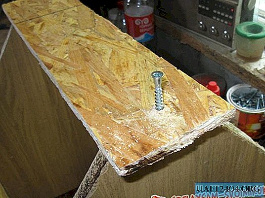
This is common, it is on a positive bus. It is highly desirable to fix the wire on the motor housing, for this you can drill a couple of millimeter holes and press this cable with a copper bracket. When the pump is ready, a curved hose is put on its nozzle with an internal diameter of at least 8 mm. and 20 cm long through which watering will be carried out. Now you can make a printed circuit board and solder the device.
The board is made of one-sided fiberglass by the LUT method.
I draw your attention to the fact that the picture of the trace and the layout of the printed circuit board is not mirrored in order to make it easier to verify during installation. When printing LUT, you need to rotate it mirrored, or use the SprintLayout file in the archive.

The board can also be painted with nail polish in this way:
The rod from the ballpoint pen is heated (a little!) Above the flame of the lighter, turning evenly, and pulling out evenly. Next, the thin end is cut with a blade. Thus, a conical tube with a very small outlet is obtained. It can be inserted inside a syringe with a volume of 1.5 cubic cm, and having previously typed a regular nail polish, draw the tracks of the printed conductors on the circuit board.
After drying, the board is lowered into the pickling solution. It can be a mixture of copper sulfate with 1: 3 salt, and water. The solution is prepared as concentrated as possible. Heating is required, for example, above the candle flame. The process is accelerated with constant stirring. Blue vitriol is sold in any agricultural store.

The microcontroller is powered by a parametric voltage stabilizer assembled on the elements D1, R7, Q1.
The value of the resistor is selected so that the own consumption of the stabilizer is as low as possible. Much lower than the so-called "Krenki".
Such a schematic solution reduced the consumption to 0.3 mA.
This is very important, since the duration of the operation of our design without recharging the batteries depends on this.
Transistor Q1 - npn is not critical.
Zener diode stabilization voltage 5.1 V. It is possible from charging for mobile. Quartz resonator - 32.768 kHz. Normal watch quartz. Of quartz watches. As keys in the circuit, MOSFETs soldered from the system board of the old computer are used. SMD LED. Can of LED strip.
Speaker - any suitable in size. You can speaker from a mobile phone.
Installation of the circuit should begin with a voltage stabilizer, and then measure the voltage at its output (capacitors C2 and C3). It should be 5 volts. Then you can solder the microcontroller and everything else.
In the circuit, unused and divorced pins of the ports of the microcontroller PB0, PB1, PD6 can be used to connect peripherals.
The microcontroller program algorithm is constructed as follows.
The controller is configured to work in asynchronous mode. Interruptions occur once per second, at this time the program counts the time, flashes for a short time with an LED (every 10 seconds) and immediately goes into sleep mode to save power consumption. If the hour counter becomes equal to zero (immediately after the reset by the button or after 24 hours), the controller's power supply is measured four times and compared with the internal voltage reference source. If the voltage is lower than the permissible one, the circuit emits periodic sound signals informing of a low battery, after fifteen signals the controller is set to power down mode and goes into sleep mode until the next recharging of the batteries.
If the voltage is above the threshold value, a sound signal is triggered and the LED lights up. Next, the initial position of the motor rotor is set and short-term pulses are sequentially applied to the motor windings. The duration of the pulses and the pauses between their succession are gradually reduced, thus a set of revolutions of the motor and further constant rotation of the blade, thereby providing an exact portion of watering. The LED flashes synchronously.
At the end of irrigation, the circuit again goes into standby mode for counting time. In this mode, it is located most of the time, this ensures high efficiency of energy consumption (about 0.3 mA).
During the main program, the controller is clocked from the internal oscillator with a frequency of 8 MHz, and in sleep mode - the external clock quartz allows you to accurately calculate the time.
Short flashes of the LED every 10 seconds signal the operation of the device. From the beginning of the zeroing of seconds, it will flash 30 minutes, and then the flashes will stop for 12 hours and resume after another 12 hours. Thus, if you set the watering at 00 o’clock, the flicker will not occur at night, but only from 12 o’clock in the afternoon.
Firmware file Dviglo_mega_avr_V.hex
When flashing, you need to configure the Dviglo_mega_avr_V.rar file for operation from the internal RC oscillator of 8 MHz sources in the VR Studio program
If you have an arduino board, you do not need a programmer. (detailed instructions)
Files in the proshivka_arduinoi folder.
When flashing, you need to configure the Dviglo_mega_avr_V.rar file for operation from the internal RC oscillator of 8 MHz sources in the VR Studio program
If you have an arduino board, you do not need a programmer. (detailed instructions)
Files in the proshivka_arduinoi folder.
Archive with materials for the article. Available for download only to registered users.
Attention! You do not have permission to view hidden text.

Video device operation:
Share
Pin
Tweet
Send
Share
Send