Share
Pin
Tweet
Send
Share
Send
This year, when a charger was needed, it turned out that it had become unusable - the contacts were rusty and began to “punch” onto the case. Due to the fact that the enthusiasm of amateur radio activity has decreased over the years, I decided to buy an impulse - automatic, so that there is less trouble - I turned it on (when needed), turned it off (when the charge stopped), and forgot it until the next need. The choice of pulse chargers is quite large, but it seems that Chinese friends have successfully finalized Danish or Italian radio circuits, as a result of which modern devices differ only in build quality. In many manuals, complete nonsense is replicated: "... the device automatically cleans the terminals of sulfates ..." - it seems that people who don’t know the difference between the terminals and the anode of the battery reprimand this balcony, where sulfation just happens (Pb2SO4 + H2SO4 + O, equal to 2PbSO4 + H2O). This process, amplified by a discharge, causes the destruction of the electrode, and a pulsed charge seems to remove, or reduce sulfation.
So, there are no fundamental differences between pulse chargers - automatic devices (everyone writes about seven- or nine-stage charging, in my opinion this is a pure advertising move, all the more there remains the possibility for a further flight of thought, such as twenty-stage, thirty-stage , etc.), therefore, based on the battery power, you need to choose what is cheaper. In my case, this is a device with an absurd name for the Aggressor charger (AGR / SBC-080 Brick) at a price for 02.2016. 2750 rubles with a desulfation function and a charge current of up to 8A, designed to charge batteries up to 160 amp.h ...


The device looks solidly outwardly - good thick (but terribly smelly) plastic, because of the well-fitted rubber gasket there are no complaints about the seams, the device is intuitive, but there is one “BUT” - there is no indication of voltage and current strength. In some cases, the “winter” charge with a current of 8A automatically jumps to a charge of 2A (motorcycle battery), while the LEDs show a charge, and an additionally connected ammeter indicates its absence. Chargers with an indication of current and voltage cost an order of magnitude more expensive - within $ 200, meanwhile, a simple refinement of any, I emphasize, any charger using an ampervoltmeter, for example, for 250 - 300 rubles, will turn your device into a more attractive and convenient in use equipment.
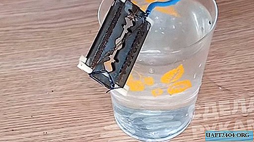
The ampervoltmeter can be located either in the charger itself (if there is space for it), or outside it in a special box, connecting it to the wires going to the battery for charging. To select a place, we will conduct an audit of the charger, for which we squeeze the side plastic linings and unscrew 6 screws. Having removed the cover, it is clear that the ampervoltmeter cannot be placed on the front panel - otherwise the board will have to be changed. To output the ammeter to the rear panel, there are several places, I chose closer to the charging cables.


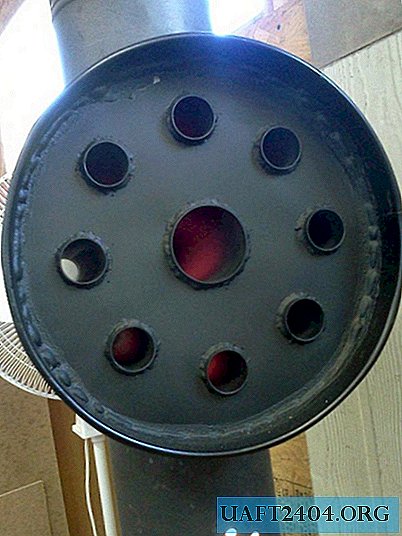
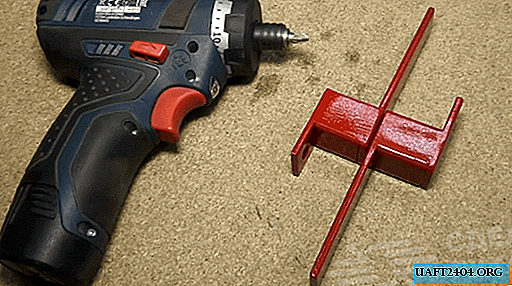
The approximate location of the ampervoltmeter. Having cut the case of the ampervoltmeter a little with slices, I positioned the device as conveniently as possible inside the case (somewhat to the left of the middle line), then gently turned the charger over, saving the place where the amvoltmeter would be installed in the charger case and outlined a hole. Further, the matter of home appliances - in 15 minutes I drilled about 40 holes with a drill or screwdriver using a drill or screwdriver on the inside of the outlined rectangle, combined them with the same drill and released the window for the ampervoltmeter. Having adjusted the edges with a file, he installed an ampervoltmeter in the window and fixed it with hot-melt adhesive. The ampervoltmeter is densely and rather firmly located in the window, does not protrude beyond the limiter, while almost all information on the rear side has been preserved.


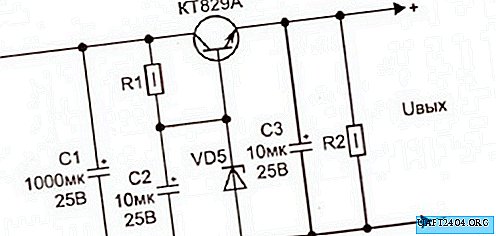
Then, cutting (-) the negative cable of the charger (black), solder the black wire of the ammeter to the top (the ammeter has two thick wires - red and black), and to the bottom of the wire going to the battery - the red wire of the ammeter and the black wire of the voltmeter. We solder the red and yellow wires of the voltmeter to the bare (+) positive lead of the charger (there are three wires of the voltmeter — yellow, red and black, they are thinner). We close the soldering places with heat shrink, or with electrical tape, and you can start charging.
By connecting the terminals (+) and (-) to the battery, on the display of the ampervoltmeter you can see its voltage, and the charge current will appear after the device is turned on and the mode is selected.


There is one inconvenience - the mode switch button is on the front side, and the ammeter is on the back, but this only begs a little alteration. As you can see, the alteration did not touch on the circuit diagram, but only touched the cables going to the rechargeable battery, in connection with which the external option for arranging the ammeter in a small case is possible for this charger and any other.
Sincerely, Vadim Zakharov.
Share
Pin
Tweet
Send
Share
Send