Share
Pin
Tweet
Send
Share
Send
Perhaps this simple device will be the tool that will confuse the kidnapper, who hopes that everywhere there are "cool" anti-theft.
The scheme works as follows: anti-theft included. An attacker opens the door, turns on the ignition, starts the engine and is glad that he succeeded. But suddenly the engine stalls. He starts it again, but after 5 - 15 seconds (depending on how you adjusted the anti-theft device), the engine stops again and there is a feeling that there are problems with the fuel system. But he will not find a malfunction, since the time relay blocks the engine ignition system with a delay of the blocking time, and not the fuel one.
The proposed anti-theft device, in fact, is a relay with a delay time on.
Here is his diagram
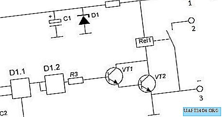
Parts are used for this device.

- Chip D1 - K176LA7 or its imported analogue CD4011.
- Transistor VT1 - KT315 with any letter or import 2SC634, 2SC633, BFP722, 2N2712, BFP720, BFP721, BFP719.
- Transistor VT2 - KT815 or BD 135, BD 139, BD 137.
- Capacitor C1 - 33 MkF 25 volts.
- Capacitor C2 - 10 - 20 MkF 25 volts. This capacitor is the time setting, this means that the time delay until the relay is turned on depends on its capacity. With a capacitor of 10 MkF, the time is about 7 seconds, and 20 MkF is about 15 seconds, but this also depends on the resistor R1, which is also a component of the time of the master circuit - R1 - C2 and the time also depends on its resistance.
- R1 is about 300 Kom, but I set the potentiometer to 680 Kom in order to be able to demonstrate a change in the delay before relay Rel1 is turned on, depending on the value of its resistance. In the finished device, when you decide what time delay suits you, the potentiometer can be replaced by a constant resistance equal to the resistance of the potentiometer.
- R2 - 100 Ohms.
- S1 - any toggle switch, switch, which you like. It will be securely hidden in the passenger compartment.
- A toggle switch is connected to terminal 1, and a toggle switch is connected to a wire that receives power after turning on the ignition switch.
- Terminal 2 connects to the ignition interrupter wire. When the device is turned on, the anti-theft relay contact closes the breaker wire to ground and thereby shuts off the engine.
- Terminal 3 is connected to ground.
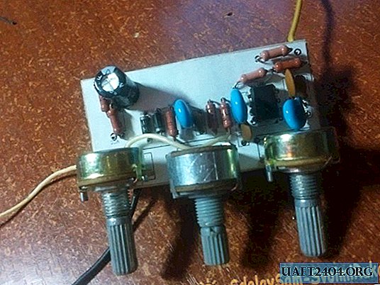
- It’s better to make the device on a breadboard, it’s easier and faster.
Device assembly


We solder the wires to the toggle switch and potentiometer and connect them to the circuit.


We connect the finished device to a 12 volt battery.

The anti-theft device works.

The device board must be placed in the case and filled with sealant to avoid mechanical damage and short circuits.
Watch the video, which shows the dependence of the delay before turning on the relay on the resistance of the potentiometer.
Share
Pin
Tweet
Send
Share
Send